If like me, you want
to record music (or wathever) from the radio or another source when you are
away or sleeping, you will end up with a MD with one very long track (up to
320 minutes in MDLP 4) which is not very convenient !
The solution :
Almost every Sony
Minidisc deck allows you to add a track mark while you are recording something
by pushing the REC button. What we will do is simulate electronically the
push of the record button at a user defined interval. So when a 80 minutes
MD is recorded in LP4, you will have 107 tracks if you (like me) choose a
delay of 3 minutes, wich will allow you to skip songs or adverts you don't
like when you will play the minidisc...
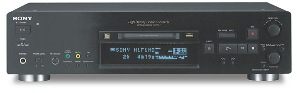
I did this project
on my Mini Disc Recorder MDS JB940
I record from Solar Radio on my Humax 5100 satellite receiver
on Astra 2 every night
What do you need
?
Very basic electronic
knowledge, a screwdriver, a soldering iron, etc...
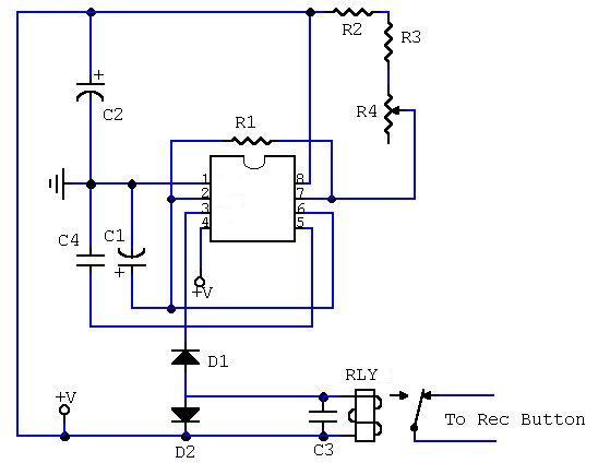
The theory
The 555 ic sends a
pulse (approx. 0.5 sec) at a user-definable period (I used 3 minutes for mine)
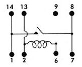
to the reed relay wich acts just like a switch. We will connect the output of
the reed relay to the pins of the record button inside of the deck, on the PCB
circuit.
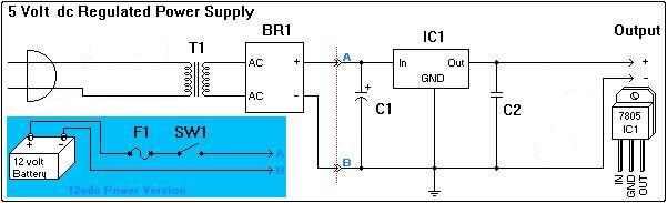
Let's make it !
You can maybe take
5 Volts inside your deck to avoid building a regulated power supply but I did
not tried this for obvious reasons.
IC1 : 555 (CMOS Version)
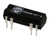
RLY1 : VR05R051 'A or Equivalent 5 Volts Reed Relay
C1 : 100µF C2 : 47µF C3 : 100n C4 : 10p all 16V
D1 & D2 : 1N4148 or 1N914
R1 : 22K R2 & R3 : 1M R4 : Trim 500K All 1/4 watt or more
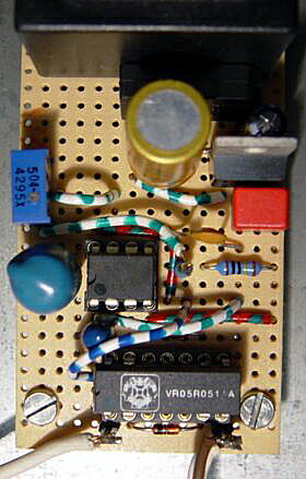
A little piece of perfored board
More info about the 555 IC here, there and the data sheet in .pdf (128 K)
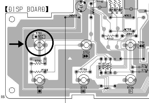
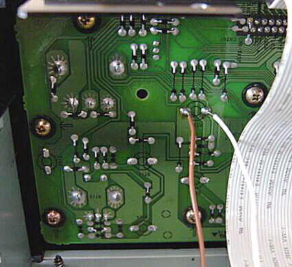
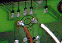
Where do I solder the two wires inside my deck ?

Open your deck (remember this could void your warranty!)
 and look for the keyboard/display pcb just on the back of the record button.
You will find very easily the two pins of the record button, just solder properly
the two wires, find a way out for them and close your deck again.
Here is an example on the MDS JB920
PCB
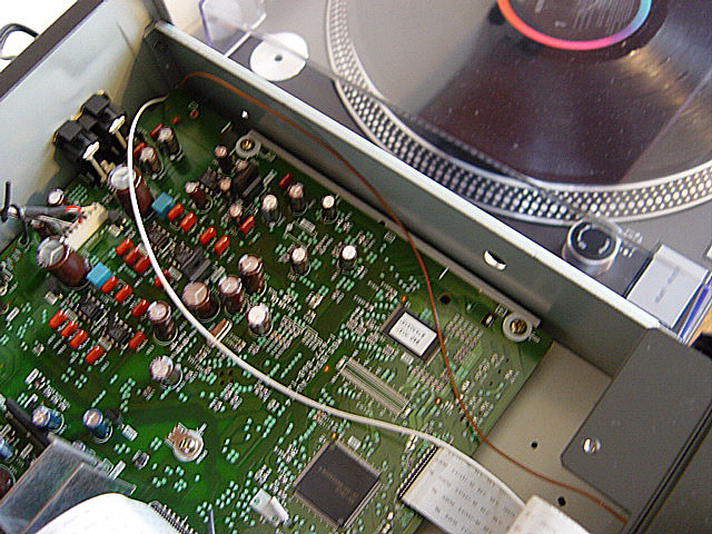
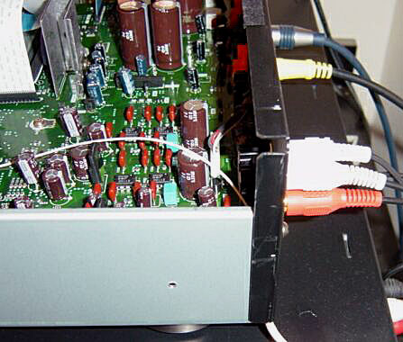
Some photos of my MDS JB940 :
Notes
You can experiment
with different value of C1 and the 3 resistors R2+R3+R4 for longer or shorter
delay.
To get a
3 minutes delay, experiment with the value of the R4 trimmer.
Also, there
are programs that will calculate the delay for you (Windows), dowload one of
them here
You can put
the circuit in the Timer case if it is big enough or in a plastic box.
It is best to take the main power at the same
source as the deck so they wake up togeheter !
Due to the 555 design, the first pulse will take
longer than the following one. For a delay of 3.00 minutes, the first track
is 4.50 minutes.
The accuracy of the circuit at startup is about
1 or 2 seconds maximum for a 3 minutes delay but after about half an hour, you
get a stable 3.00 minutes delay.
You can put a switch between the relay and the
record button for non timer usage.
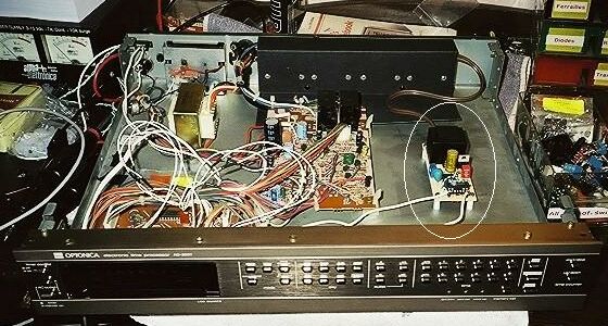
For automatic
operation with my Sharp Optonica Timer (from 1981 !), I put the 1 wire of the
output relay via the Outlet "A" ON/OFF switch (bottom left on the
photo below) which is a double inverter (6 poles) with one side not connected.
So I connected the wire from the relay (it doesn't matter wich one of the two
!) to that unused side of the inverter and when I switch the deck ON manually
the MDS JB940 by pushing the Timer button "Outlet A", the deck will
not receive the pulse from the relay (for normal operation) . If the deck is
switched ON by the timer, the Outlet A swtch is not pushed and then the
inverter will pass the contact between the relay and the record button for Auto
Track Mark.
I also put a on/off switch at the back of the
Timer to allow me to force the pulse to pass even if I switched manually the
Outlet A switch.
Of course, it all depends of the Timer you use
!
Let's just hope that Sony will include this function
in their future deck, like they just did on their MZ-N10
Sharp Optonica timer
with the Auto Track Mark inside :
I hope I did
not make any mistake on this page !
Do all this
at your own risk but don't worry, I've got e-mails from all over the world telling
me this circuit work great !
I've done
my best to make all this as clear as possible but if you have any questions...